Project Settings

Project Settings Tab
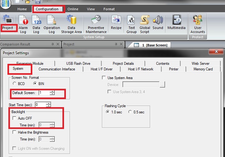
You learned under the previous tab called Start that you could go into the Project Settings. You can go into the Project settings at any time by by going to Configuration tab and selecting Project. You had selected the communication and Host I/F Network tab. Now if you select System than you can further set up the HMI.
You will notice that there is a Default Screen selection where you can set what base screen to select on power up. You can also se if the backlight should go out after a fix amount of time.
Another important setup is to go over System Area. This special ara is used by the developer to combine functions in the PLC and the HG screen through specific memory storage locations.
Typically the system areas are used to store the HG screen control and error data. Selecting this function and entering a device number ( such as D10) will set-up an area which is divided into 4 regions.
The regions store data for the following functions.
| System Area | #Words | Access | Function |
|---|---|---|---|
| 1 | 2 | Read/Write | Screen Control |
| 2 | 2 | Write | Errors and Data Entry Status |
| 3 | 4 | Read | Clock Data |
| 4 | 4 | Write | Clock Data |
System Area 1
Writing a decimal number to a word"0" will cause the HG unit to switch to that screen. Writing a 1 or a 0 to any individual position in word "1" will change the state of that function.
| Address | Bit | Function |
|---|---|---|
| +0 | 0-15 | Dispaly Screen |
| +1 | 0 | BackLight On |
| +1 | 1 | Blink Display 1 second cycle |
| +1 | 2 | Blink Display .5 second |
| +1 | 3 to 4 | Rserved |
| +1 | 5 | Auto Backlight Off Release |
| +1 | 6 | Beep |
| +1 | 7 | screen display |
| +1 | 8 | Rserved |
| +1 | 9 | Error clear |
| +1 | 10 | Numerical INput setting clear |
| +1 | 11 | Character INput Setting Clear |
| +1 | 12 to 15 | Reserved |
System Area 2
Reading a 1 in any individual position in words 2 and 3 indicate a specific error function or data entry function.
| Address | Bit | Function |
|---|---|---|
| +2 | 0-2 | Reserved |
| +2 | 3 | Host Communication Error |
| +2 | 4 | Reserved |
| +2 | 5 | Arithemetic Error |
| +2 | 6 | Device range error |
| +2 | 7 | Clock IC Error |
| +2 | 8 | CF Access Error |
| +2 | 9 | Printer timeout error |
| +2 | 10 | Script error |
| +2 | 11 | Reserved |
| +2 | 12 | Reserved |
| +2 | 13 | Reserved |
| +2 | 14 | Backup Data Error |
| +2 | 15 | Reserved |
| +3 | 0 | Numerical input setting complete |
| +3 | 1 | Numerical input setting cancel |
| +3 | 2 | Auto Backlight Off Being Executed |
| +3 | 3 | Printing |
| +3 | 4 | 1: Recipe data is being transferred |
| +3 | 5 | Character input setting complete |
| +3 | 6 | Character input setting cancle |
| +3 | 7-15 | Reserved |
Note: the 0th bit, 1st bit, 5th bit and 6th bit of address +3 cannot be set to "0" directly. Clear these bits by using the 10th bit and 11th bit of Address +2.
System Area 3
The system area 3 data can always be read When set to "1" the calendar data is written to the MICRO/I.
| Address | Bit | Function | Data |
|---|---|---|---|
| +4 | 0-7 | Calendar data "Month" (2 BCD digital) | 01 to 12 |
| +4 | 8-15 | Calendar data "Year" (2 BCD digital) | 00-99 |
| +5 | 0-7 | Calendar data "Hour" (2 BCD digital) | 00-23 |
| +5 | 8-15 | Calendar data "Day" (2 BCD digital) | 01-31 |
| +6 | 0-7 | Calendar data "Second" (2 BCD digital) | 00-59 |
| +6 | 8-15 | Calendar data "Minute" (2 BCD digital) | 00-59 |
| +7 | 0-14 | Reserved (write "0") | 0 |
| +7 | 15 | 0 is don't update and 1 is update | 0 or 1 |
Note: if address 7 bit is set to "1" then all data ( addresses 4,5,6) are updated.
System Area 4
Data is written from the MICRO/I to Sytem Area 4 once per minute. The MICRO/I calendar data is written to System Area 4
| Address | Bit | Function | Data |
|---|---|---|---|
| +8 | 0-7 | Calendar data "Month" (2 BCD digital) | 01 to 12 |
| +8 | 8-15 | Calendar data "Year" (2 BCD digital) | 00-99 |
| +9 | 0-7 | Calendar data "Hour" (2 BCD digital) | 00-23 |
| +9 | 8-15 | Calendar data "Day" (2 BCD digital) | 01-31 |
| +10 | 0-7 | Calendar data "Second" (2 BCD digital) | 00-59 |
| +10 | 8-15 | Calendar data "Minute" (2 BCD digital) | 00-59 |
| +11 | 0-14 | Reserved (write "0") | 0 |
| +11 | 15 | 0 is don't update and 1 is update | 0 or 1 |
Note: if address 7 bit is set to "1" then all data ( addresses 4,5,6) are updated.