HMI Tutorial
coast

Lesson 2 will cover screens. You can have up to 3000 base screens and 3015 popup screens. The base screen differs for the MICRO/I model selected. The HG3G/4G will have 800 X 600 pixels. The HG2G-5F will have 640 X480 pixels. The HG2G-5S will have 320 X 240 pixels. The HG1F has 300 X 100 pixels. The FT1A display resolution is 240 wide by 100 hi pixels


Creating Screens

robotHome Tab

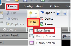
From the Home tab, in the Screens group, click under New the Base Screen. The screen screen properties dialog box is displayed and you can give it a name.


robotNew Screen

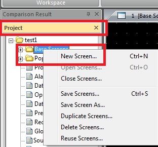
You can also create a new screen by going to Project Window and right clicking the Base Screens and selecting New Screens. If you do not see Proct Window the next step will show it.


robotProject Window

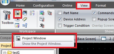
If you did not see the Project Window in previous step, just go to the View Tab and select Projet Window.
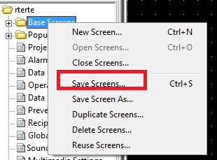


robotSave Screen

In your project window you should see both screens. You may have to save the screens. You can save with the top left button Application Menu button or you can right click on base screen in your project window and do a save screen ok.
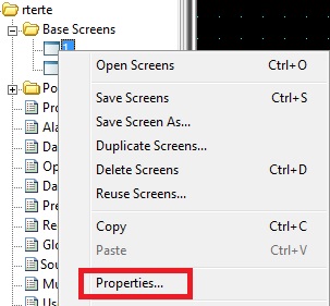


robotRename Screen

To give your base screen a name, just right click the base screen in your project window and select properties In screen properties pop up, you can give it a title.
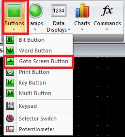


Create a Goto button

robotGoto Button

From the Home tab, in the Parts group, click Button and then click Goto Screen Button.


robotGoto Properties

Click on a point on the screen where you want the goto button to be displayed. Double click the image to get the properties dialog box to appear. For Action Mode select Switch to Base Screen. For Screen No. choose screen 1

robotSelect how button will look

Just like you did in lesson 1, you can select view in your properties screen select View and for Image Type select Picture and then select Browse. Click on Symbol Facotry Go to International symbols and select the left arrow.

robotMake button invisible

Instead of making an image for the goto button, being invisible is popular also. If you want the button to be invisible, you can select advance at the bottom of the properties screen and now under general tab will be view switching method as No image


Writing a bit to the PLC

robotBit button

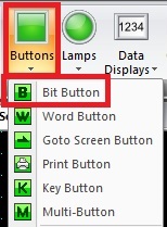
From the Home tab, in the Parts group, click Button and then click Bit Button.


robotSet

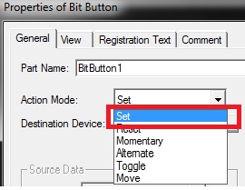
Click on a point on the screen where you want the bit button to be displayed. Double click the image to get the properties dialog box to appear. For Action Mode Set writes a 1 to the bit device. Reset writes a 0 to the bit device. Momentary sends a 1 as long as button held then goes to 0 when released. Alternate writes a 1 then a 0. Toggle inverts the bit. Move will move a value to the bit device. Select SET

robotDestination Device

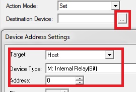
In the Destination Device select the three dot box and your device address settings should apprear. For Target select host and device type M for internal relay and address 0.


robotView Tab

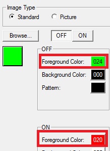
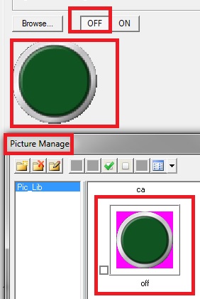
In the view tab you will select the color for when the button is off and on. You can also go to picture and select browse to import an image or use the symbol library.


robotTrigger condition

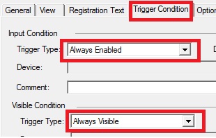
Under trigger condition tab you can set trigger type so that the button only works such as when a bit is on. For now just leave it as always enabled. Same thing for visible condition, and for now also leave it always enabled.


Reading a Bit Status

robotPilot Lamp

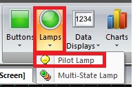
From the Home tab, in the Parts group, click Lamps and then click Pilot Lamp.


robotNo Flash

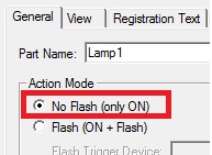
Click on a point on the screen where you want the pilot lamp to be displayed. Double click the image to get the properties dialog box to appear. For Action Mode set to non flash


robotTrigger Condition

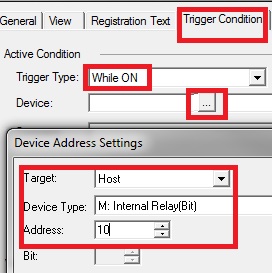
Go to the Trigger Condition For Active Condition select While on and for the Visible Condition select while on. In Active condition you will select the three dots by device and set Host to M10. This means the lamp will change state based on M10.


robotView Tab

In the view tab you will select the color for when the button is off and on. Under Image Type select picture and then Browse. Select Symbol Library and select 3G circles and select two green circles for off and on. Once the image is in the picture library, you will have to select to make it to be visible for the off and on button.