FAQ Basics
What PLCs can talk to the touch screen?
What PLCs can talk to the touch screen?
There are many PLCs that IDEC has drivers for. Here is a link to the virtual catalog that has models we can talk to: Supported Drivers If you do not see your model of PLC, check to see if it can do Modbus communication which is another way to talk to many PLCs.>
How to set up PLC to talk to HG through Ethernet
Application note
Here is a link to an application on how to set up the FC5A-D12 to a HG4G touchscreen: : Host Setup
How to sync the clock on the HG to the PLC.
 Clock Sync
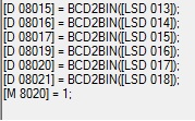
The special internal registers of the HG LSD13,14,15,16,17 and 18 and the data registers of the PLC D8015,16,17,19,20 and 21 correlate to year, month day hour, minute and second. M8020 of the PLC is a calendar write flag. You will have to use global scripting in the touch screen for the D8015 to equal the LSD13 and so on. Here is link to the file called Sync time that will show in global scripting how to do accomplish this: Sync time
How to add expansion outputs to the HG.
PLC expansion units
Chapter 29 of the user manual goes over the expansion modules but you can plug in the digital I/O modules that are the expansion units of the PLC such as the FC4A-R081 which is an 8 out relay module. The inputs will be mapped to LEX bits and the outputs are mapped to LEY bits. The addressing is in octal base so the numbers go from 0-7. The first 8 outputs are LEY 0 to LEY 7.
What is scripting?
Scripting for IDEC
The script function s a proprietary description programming language, which allows you to execute complicated operations easily. You can combine conditional statements, mathematical operators and functions to create a variety of complex processes. Here is link to the file called WindLDR Script which is for the PLC but it will be the same for the HG : WindLDRS Script
What are the Modbus Addresses for IDEC
Modbus slave address
The Modbus slave address can be found in the application notes of IDEC.com with other valuable information. Click on this link to go the Application notes: Modbus Addressing Table
What is Modbus.
Modbus Tutorial
Modbus is a method used for transmitting information over serial lines between electronic devices. Modbus is an open protocol and has become a standard communications protocol in the industry used by many companies. Here is a very good tutorial on how to set up Modbus RTU for the PLC but the HG would be similar Click here for a link for a Modbus tutorial: Modbus Tutorial
How to work Modbus with the FT1A touch?.
FT1A Touch Modbus
The Modbus for the FT1A touch goes directly into the touchscreen part of the unit. To get the Modbus to the PLC part of the unit, scripting will need to be done. Here is a link to the video tutorials that will be helpful. It can be found under PLCs Other optional settings called: Move Modbus data to Touch internal PLC
How many touchscreens can talk to one FC5A-D12.
Maximum touch screens
The maximum number of touchscreens that can communicate with a FC5A-D12 simultaneously is 11.
How do I know if my driver is installed?
 USB Driver
In your control panel under ports you should see the IDEC USB CDC. If you see other devices then the driver is not installed. Here is a link to drivers Drivers
I cannot download to my HG2G-5S
Serial setup
The HG2G-5S does not have a true USB. You must set your port to serial under setup and select the correct com port which can be found in your device manager on the PC.
Where can I find the specs to the touchscreen
Virtual Catalog
You can find the specs by typing in a model in the search window then viewing product and selecting literature or you can go to the virtual catalog. Here is a link to a page in the virtual catalog that will be the beginning of the section of the operator interface where you can find the specifications. Virtual Catalog
Where can I find how to make a cable for the operator interface?
 Communication Manual
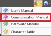
In the upper right corner of your NV2 software, you can access the manuals. In chapter two of the communications manual will cover wiring between the operator interface and the PLC. There is a section for each PLC and at the end of each section gives suggested parameter set up so it is helpful to not only look at the wiring diagrams but also the parameter setup for each PLC.